|
|
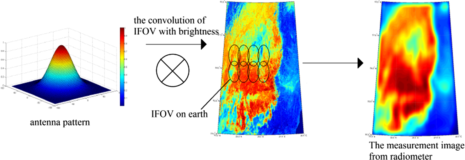
1.IntroductionThe geostationary Earth orbit (GEO) satellite is much higher than low Earth orbit (LEO), which causes a lower spatial resolution for passive microwave remote sensing. To improve its spatial resolution, submillimeter wave is desired for GEO passive microwave observation. However, the frequency ranging from 50 to 70 GHz, which is widely used in temperature sounding, is an important band in microwave remote sensing,1 which is sensitive to oxygen and thus can provide better observation of atmospheric vertical structure. Furthermore, comprehensive analysis of multiple frequencies is also necessary for GEO satellite remote sensing, but the remote sensing data of different frequencies with the same resolution are useful for users.2 Resolution enhancement is such a technique that uses redundancy measurements in low-frequency channel (over-sampled information) to achieve a measurement of higher resolution. The methods of resolution enhancement, such as the Backus–Gilbert (BG), scatterometer image reconstruction (SIR), and Wiener filter, have been introduced to increase the spatial resolution of passive microwave remote sensing image. The BG method is an antenna-pattern deconvolution technique that obtains an inverse matrix, which is to be convolved with the measurement data to reconstruct brightness temperature.2–6 The SIR algorithm is a variation of the multiplicative algebraic-reconstruction technique which could find the optimal estimate of brightness temperature by iterative algorithms.7–9 The Wiener filter method using filter and Fourier transform theory to invert the convolution processing in measurement could also reconstruct the brightness temperature.10–12 These methods have been widely used in microwave radiometer data from LEO. Recently, Wiener filter and SIR methods were applied to GEO satellite imagery.13 But in this application, the Wiener filter matrix which was used for deconvolution did not change for a whole image in the processing of brightness temperature reconstruction. Compared with the LEO satellite, the influence of Earth curvature on GEO satellite image is much greater, which causes obvious distortion of the footprint, especially in the locations far from subsatellite point (SSP). The observation interval and footprints of microwave radiometer should not be considered to be changeless in every scan. The distortion of pixels position can be alleviated by resampling, but the impact of Earth curvature on pixel itself existed and was not discussed in the above applications. Actually, in GEO radiometer measurement, the properties of convolution are affected by the variation of microwave radiometer footprints. In this article, we improved Wiener filter method using a projective spherical coordinate system, which achieves higher resolution by considering not only the location of the pixel but also the pixel itself. We first give a brief introduction of Wiener filter method and the projective spherical coordinate system. Next, we present the background and evaluation method of the simulation. Analyses of the simulation results are also made in this section. 2.Method DescriptionFigure 1 describes the observation of a microwave radiometer, which can be presented by integrating the products of the ground brightness temperature and the instantaneous field of view (IFOV) of antenna pattern below: where denotes the antenna temperature in location () and stands for the brightness temperature on the ground is the IFOV of the antenna pattern corresponding to the observation location (). In the above expression, and denote the spherical coordinates on Earth (and Earth is assumed to be a sphere); and are the coordinates for the observed location.Based on Eq. (1), Wiener filter method is used to reconstruct Earth surface brightness temperature from antenna temperature . 2.1.Wiener Filter MethodWiener filter method applies deconvolution on antenna temperature to obtain higher spatial resolution images. Assuming that IFOV is invariant in the observation, , which is independent with observed location can be expressed by . Equation (1) can be expressed as convolution of and , where defines the convolution and is the noise of radiometer. Then, applying Fourier transform on the both side of Eq. (2), we obtained where , , , and are Fourier expressions of , , , and , respectively. Finally, an inverse operator is used to reconstruct the ground brightness temperature :Generally, the solution to a convolved problem as in Eq. (2) needs an optimization method such as least-squares to prevent unstable solutions.14 In Wiener filter, the method of minimizing the mean square error is used as the constraint condition to obtain optimum solution of the problem. According to Wiener filter method, the inverse operator is given below: where is the noise of radiometer15 and is the power spectrum of the image .2.2.Proposed MethodHowever, in the case of GEO satellite, the prerequisite of convolution is unsustainable since IFOV changes in each observation. Figure 2(a) shows different IFOV surfaces (the plane tangent to the surface) of antenna pattern in different location. In the Earth case, IFOV on point A can be calculated through the projection of antenna pattern on Earth surface. If A is far from SSP, the projected surface on Earth will not be perpendicular to the line O’A, i.e., the IFOV, changing from circle to ellipse, as shown in Fig. 2(b). And the ratio of the major axis to the minor axis of the ellipse is determined by the angles and . Since the angle between IFOV surface in point A and line O’A is , the ratio of the major and minor axes of the ellipse can be calculated as following: Fig. 2Diagram of different surfaces on Earth and the projective sphere. (a) Geometry of instantaneous field of view (IFOV) surface in different location. (b) IFOV in nadir and off-nadir on Earth and the projective sphere. (c) The coordinate transformation between Earth and the projective sphere.  Due to the effect of geometric distortion, IFOV of antenna pattern keeps changing with observed location moving. The deformation becomes more evident as the incidence angle increasing. Although in a limited area, this change is negligible, it can break the convolution prerequisite for implementing deconvolution. To correct the distortion, we propose a projective sphere coordinate system. The projective sphere is centered in the satellite and owns a proper radius (the length of radius makes no difference to calculation results provided that it is less than the distance from satellite to SSP). Furthermore, our aim is to obtain a fixed IFOV by using point-by-point projection from Earth to the sphere. As shown in Fig. 2(a), in the proposed sphere, O’A’ is the radius of the projective sphere, and the IFOV surface is always perpendicular to O’A’. Because of this perpendicular relationship in the projective sphere, a changeless IFOV on the projective sphere can be achieved. As shown in Fig. 2(c), there are two coordinate systems in space. Let () presents the spherical coordinate of Earth, and () presents the new coordinate of the projective sphere. Also, when radiometer antenna observes in the location on Earth, the corresponding projective point in the sphere is presented as . The proposed method can be processed by the following steps. In the first step, every pixel of original image and IFOV is marked with its ground location coordinate () for the preparation of projection transformation. In the second step, the projective transformation is applied to the Earth coordinate to get the coordinate on projective sphere. The two-dimensional position of () is projected onto the projective sphere with new coordinate system (). The expression of projection transformation is the below: where is the ratio of distance to Earth radius.In the new coordinate system, Eq. (2) can be written as following: where , , , and come from , , , and , respectively after projection transformation.At last, the deconvolution method is applied on Eq. (9) to get reconstructed brightness temperature on the projective sphere. The brightness temperature on Earth is obtained by inverse projection transformation on . In this section, a projective sphere is introduced into Wiener filter method to preserve the convolution process in GEO satellite observation. The simulated results, in Sec. 3, show that the proposed method using projective sphere outperforms original Wiener filter method in resolution enhancement. 3.Simulation ResultsBefore the simulation results are shown, the details of the background and the evaluation methods of images are introduced as follows. 3.1.BackgroundThe coordinates of latitude and longitude (denoted by “lat” and “long”) are the relative value to the location SSP. Here, the coordinate of SSP is assumed to be (0°E, 0°N). In this simulation, the observation is set in the location of (0°E, 0°N), (25°E, 25°N), and (35°E, 35°N) on Earth. The coordinate of a location can be transformed from the sphere coordinate system (denoted by and ) by the expression as below: Since a GEO radiometer image is unavailable currently, the observed brightness temperature has been simulated by convolution of the antenna pattern with a given scene provided by a LEO remote sensing satellite (if this true). The spatial resolution of remote sensing images is 1 km, and the area is , as shown in Figs. 3(a)Fig. 4–5(a). Fig. 3Resolution enhancement in (0°E, 0°N): (a) Brightness temperature. (b) Antenna temperature. (c) Method A. (d) Method B. (e) Correlation coefficient of Method A. (f) Correlation coefficient of Method B.  Fig. 4Resolution enhancement in (20°E, 20°N): (a) Brightness temperature. (b) Antenna temperature. (c) Method A. (d) Method B. (e) Correlation coefficient of Method A. (f) Correlation coefficient of Method B. 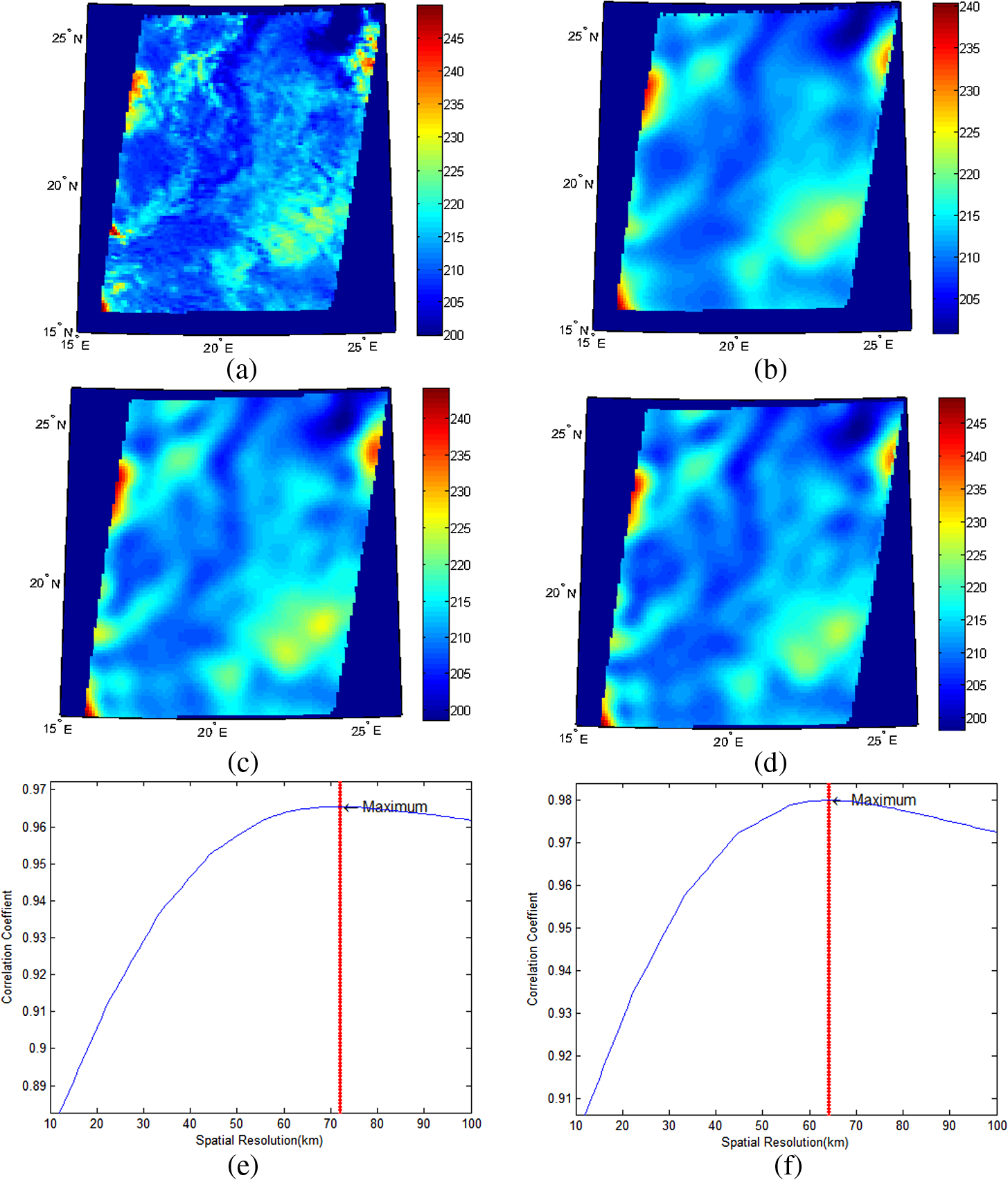 Fig. 5Resolution enhancement in (35°E, 35°N): (a) Brightness temperature. (b) Antenna temperature. (c) Method A. (d) Method B. (e) Correlation coefficient of Method A. (f) Correlation coefficient of Method B.  In this article, the diameter of antenna is assumed to be 2.7 m, with 0.15 deg half-power beamwidth of antenna pattern at 54 GHz, which can provide about 94-km spatial resolution at SSP. The distribution of normalized antenna pattern is assumed to be a bidimensional Gaussian function. The scan interval of the satellite is 10 km in SSP, and the angular velocity of microwave radiometer scanning is steady in some measurement area. The height of GEO is 36,000 km, and the shape of Earth is assumed to be a sphere with radius of 6400 km. The noise of microwave radiometer is 0.5 K with Gaussian distribution. For comparison, the original Wiener filter method is called method A in the simulation. The proposed method introduced in Sec. 2 is called method B, which uses Wiener filter method in the projected sphere. 3.2.Method of EvaluationSpatial resolution and synthetic index are used to evaluate the performance of resolution enhancement. Here, the expression is applied to calculate spatial resolution, where and denote the lengths of minor and major axes of the IFOV. The correlation coefficients between image after enhancement and the images convolved by different IFOV [according to Eq. (2)] are calculated. The spatial resolution of enhanced image is defined as the resolution of convolved image that has the maximum correlation coefficient . The correlation coefficient of two images can be denoted as below: where and denote the two compared images, and can be expressed as where and denote the corresponding pixels of image and image ; and are the mean values of the pixels of image and .The synthetic index (Ref. 13) indicate the improvement of the output image , where and and stand for the brightness temperature of the Earth surface, the antenna temperature before and after resolution enhancement, respectively. 3.3.Analyses of Microwave Radiometer Data after Resolution EnhancementIn this simulation, two methods are implemented on those GEO images to reconstruct their brightness temperature. The brightness temperature images of Figs. 3(b)–5(b) denote the observation results from GEO with spatial resolution of 94, 104.8, 131.9, and 104.8 km, respectively, according to different mentioned in Sec. 3.2. Comparing the remote sensing images after enhancing [as shown in Figs. 3(c)–5(c) and 3(d)–5(d)] with different methods, method B can provide higher performance results especially in (35°E, 35°N), which could restore more details than method A. Also, the correlation coefficient of method A and method B with the images convolved by different IFOV is provided by Figs. 3(e)–5(e) and 3(f)–5(e). The evaluation of above figures is shown in Table 1. From Table 1, it is known that the value of spatial resolution before and after reconstruction for the two methods are 71.33 and 64.64 km at the area of (20°E 20°N), and 89.78 and 67.33 km at the area of (35°E 35°N). Method B provides obvious improvement in spatial resolution after enhancement. The synthetic index in each case is bigger than 1, which indicates that the reconstructed images have better relationship with the scene of the Earth surface. In the case of (20°E 20°N) and (35°E 35°N), correlation coefficient of method B is bigger than Method A, whereas in (0°E 0°N) the parameter of the two methods is similar. At SSP, the two methods provide nearly the same results, because the change of IFOV on Earth is little in this area. Table 1Comparison of resolution enhancement of remote sensing images for two methods.
4.ConclusionIn this article, a projective spherical coordinate system is proposed to correct the geometric distortion in GEO resolution enhancement with the Wiener filter method. The sphere provides invariant inverse deconvolution matrix in the Wiener filter method to improve the spatial resolution, which performs better in the location (35°E 35°N), which is influenced by Earth curvature more significantly. It is found that in this region, the IFOV of antenna on Earth changes gradually in observation, which reduces the performance of deconvolution. However, in the projective sphere, the IFOV remains unchanged, which causes better performance for Wiener filter method. In implementation of this method, low-resolution image of microwave radiometer is transformed onto the projected spherical coordinate system first, and then the filter matrix is obtained through coordinate transform. Furthermore, the deconvolution is applied to the image in this spherical coordinate system. Finally, the deconvolved image is transformed into Earth coordinate system. To evaluate this method, the original Wiener filter is used for comparison in the simulation. The results prove that this projective coordinate system can improve the performance of resolution enhancement of microwave radiometer data using Wiener filter method, especially at the position far away from SSP. AcknowledgmentsThis work was supported by the National Natural Science Foundation of China under Research Grant 41105007. ReferencesB. BizzarriA. Mugnai,
“Requirements and perspectives for MW/sub-mm sounding from geostationary satellite,”
in Proc. 4th EGS Plinius Conf.,
(2002). Google Scholar
M. R. FarrarE. A. Smith,
“Spatial resolution enhancement of terrestrial features using deconvolved SSM/I microwave brightness temperatures,”
IEEE Trans. Geosci. Remote Sens., 30
(2), 349
–355
(1992). http://dx.doi.org/10.1109/36.134084 IGRSD2 0196-2892 Google Scholar
A. Stogryn,
“Estimates of brightness temperatures from scanning radiometer data,”
IEEE Trans. Antennas. Propag., AP-26
(5), 720
–726
(1978). http://dx.doi.org/10.1109/TAP.1978.1141919 IETPAK 0018-926X Google Scholar
G. A. Poe,
“Optimum interpolation of imaging microwave radiometer data,”
IEEE Trans. Geosci. Remote Sens., 28
(5), 800
–810
(1990). http://dx.doi.org/10.1109/36.58966 IGRSD2 0196-2892 Google Scholar
P. BauerR. Bennartz,
“Tropical rainfall measuring mission microwave imaging capabilities for the observation of rain clouds,”
Radio Sci., 33
(2), 335
–349
(1998). http://dx.doi.org/10.1029/97RS02049 RASCAD 0048-6604 Google Scholar
P. Chakrabortyet al.,
“Brightness temperature reconstruction using BGI,”
IEEE Trans. Geosci. Remote Sens., 46
(6),
(2008). http://dx.doi.org/10.1109/TGRS.2008.916082 IGRSD2 0196-2892 Google Scholar
D. G. LongP. J. HardinP. T. Whiting,
“Resolution enhancement of spaceborne scatterometer data,”
IEEE Trans. Geosci. Remote Sens., 31
(3), 700
–715
(1993). http://dx.doi.org/10.1109/36.225536 IGRSD2 0196-2892 Google Scholar
D. G. LongD. L. Daum,
“Spatial resolution enhancement of SSM/I data,”
IEEE Trans. Geosci. Remote Sens., 36
(2), 407
–417
(1998). http://dx.doi.org/10.1109/36.662726 IGRSD2 0196-2892 Google Scholar
D. G. LongM. W. SpencerE. G. Njoku,
“Spatial resolution and processing tradeoffs for HYDROS: Application of reconstruction and resolution enhancement techniques,”
IEEE Trans. Geosci. Remote Sens., 43
(1), 3
–12
(2005). http://dx.doi.org/10.1109/TGRS.2004.838385 IGRSD2 0196-2892 Google Scholar
R. SethmannG. HevesterB. A. Bums,
“Image deconvolution techniques for reconstruction of SSM/I data,”
in Proc. IGARSS,
2377
–2380
(1991). Google Scholar
R. SethmannB. A. BurnsG. C. Heygster,
“Spatial resolution improvement of SSM/I data with image restoration techniques,”
IEEE Trans. Geosci. Remote Sens., 32
(6), 1144
–1151
(1994). http://dx.doi.org/10.1109/36.338362 IGRSD2 0196-2892 Google Scholar
B. BizzarriF. Di PaolaS. Dietrich,
“Resolution enhancement of millimetre-submillimetre wave images from geostationary orbit,”
(2005). Google Scholar
S. DietrichF. Di PaolaB. Bizzarri,
“MTG: Resolution enhancement for MW measurements from geostationary orbits,”
Adv. Geosci., 7 293
–299
(2006). http://dx.doi.org/10.5194/adgeo-7-293-2006 69IPIS 1680-7340 Google Scholar
G. PanJ. LinG. Cheng,
“Wavelet based deconvolution algorithm for time domain near-field ISAR imaging,”
IEEE Trans. Antennas. Propag., 55
(7), 2013
–2021
(2007). http://dx.doi.org/10.1109/TAP.2007.900235 IETPAK 0018-926X Google Scholar
A. BuadesB. CollJ. Morel,
“Neighborhood filters and Pde’s,”
Numerische Mathematik, 105
(1), 1
–34
(2006). http://dx.doi.org/10.1007/s00211-006-0029-y Google Scholar
BiographyDawei Liu received his BS and MS degrees from Wuhan University, Wuhan, China, in 2001 and 2004, respectively, and his PhD degree from the Chinese Academy of Sciences, Beijing, China, in 2007. He was with the Electromagnetics Academy, Zhejiang University, Hangzhou, China. He is currently with the School of Electronic and Information Engineering, Beihang University, Beijing. His research interests include the electromagnetic modeling of microwave remote sensing, electromagnetic theory, and data analyses. Kai Liu received his BS degree in electrical engineering from Beihang University, Beijing, China, in 2011, and is currently working toward his PhD degree in electromagnetic field and microwave technique at Beihang University. His current research interests include resolution enhancement and retrieval algorithm. Changchun Lv received his BS degree in electrical engineering from Jishou University, in 2010, and currently is working toward his MS degree in electromagnetic field and microwave technique at Beihang University. His current research interests include millimeter wave antenna and near-field electromagnetics. Jungang Miao received his BSEE degree from the National University of Defence Technology, Changsha, China, in 1982, his MSEE degree from Beijing University of Aeronautics and Astronautics (BUAA), Beijing, China, in 1987, and his Dr. rer. nat. in physics from the University of Bremen, Germany, in 1998. His research areas are electromagnetic theory, microwave engineering, and microwave remote sensing of the atmosphere, including sensor development, calibration, and data analyses. |