
|
|
1.IntroductionIn recent years, space targets (e.g., rocket bodies, fragments of satellites, ballistic warheads, etc.), especially space debris, are fast becoming a threat to aerospace activities.1,2 Generally, a space target has a complex micromotion, such as spinning, precessing, and rolling, in addition to the body translation.3,4 These micromotions will produce additional frequency modulation on the radar echo signal, which is called the micro-Doppler effect.5–7 The micro-Doppler signature describes the characteristics of the micromotion target and reflects the transient behavior of the Doppler frequency shift, which provides important information for space target recognition.8 Therefore, since the concept of micro-Doppler was proposed, micromotion feature extraction has attracted much attention in research.9–12 Micro-Doppler feature extraction of the micromotion is usually implemented based on a time-frequency analysis technique. Based on this, an estimation method of the motion parameters was proposed in Ref. 13, and an adaptive chirplet representation for feature extraction from targets with rotating parts was analyzed in Ref. 14. A feature extraction based on empirical-mode decomposition (EMD) was proposed in Refs. 15 and 16. Also, image processing algorithms, such as the Radon transform17 and Hough transform,17–19 have been introduced for the micromotion feature extraction. However, these methods need a long observation time and high pulse repetition frequency (PRF), because the time-frequency distribution (TFD)-Hough requires at least one-half or one full rotating period to successfully extract the micromotion feature.18 For example, assuming that the rotating radius is 5 m, the rotating frequency is 3 Hz, and the carrier frequency of the radar is 1 GHz, then the PRF must be higher than 1260 Hz to avoid the frequency-domain aliasing phenomenon of the micro-Doppler signal. However, a phased array radar has to simultaneously serve different activities and the long-observation time and high PRF needed would place a great demand on the radar resources. On the other hand, the micromotion feature extraction is independent of the signal bandwidth. Hence, if the micromotion feature extraction of the radar target can be implemented with a narrow-band tracking pulse, then there is no need to allocate additional fixed radar resources for this task. Therefore, it will lighten the demand on the radar resources and the efficiency of the radar can be significantly improved. This is the motivation of this paper. The radar target tracking period is usually relatively long. As such, the bandwidth of the micro-Doppler signal is relatively wide, which will create frequency-domain aliasing and make micromotion feature extraction difficult. To solve the problem, a varying PRF method20 can be utilized to eliminate the aliasing. Broadly speaking, although the PRF for the tracking pulse is relatively low, micromotion feature extraction can be implemented through changing the PRF of the tracking pulse. However, in the case of a varying PRF, existing micromotion feature extraction algorithms, such as the time-frequency techniques, the Hough transform, the EMD algorithm, etc., will not function properly. In this paper, an orthogonal matching pursuit (OMP) algorithm is used to complete the micromotion feature extraction of targets via constructing a corresponding atom set of the micro-Doppler signals. Furthermore, since the rotating radius and initial phase of a micromotion scatterers can be estimated by the OMP algorithm, we can obtain the two-dimensional (2-D) distributed image of the target scatterers. Because the rotating radius and rotating frequency are not known a priori, it is not possible to develop an algorithm to determine the optimal PRF. Thus, the simplest way to find the most suitable PRF is by first estimating the dominant micro-Doppler frequencies of all micromotions and using them to formulate a scheme for a varying PRF. However, this action itself is also a waste of the radar resources. Therefore, an adaptively varying PRF method is proposed in this paper to further improve radar efficiency. In this method, through constructing the atoms set at the prevailing tracking data rate, the target image quality is assessed and fed back to the radar system to guide the adjustment of the PRF of the tracking pulses and the reconstruction of the dictionary atoms. This paper is organized as follows: The analysis of the radar echo of micromotion target and the micromotion feature extraction with varying PRF sampling based on OMP are illustrated in Sec. 2. The micromotion feature extraction method using tracking pulses with an adaptive PRF is proposed in Sec. 3. Simulations are presented in Sec. 4 to validate the effectiveness of the proposed method, and some conclusions are made in the last section. 2.Micromotion Feature Extraction of Radar Target with Varying PRF Sampling2.1.Analysis of the Radar Echo of Micromotion TargetTaking a spinning target as an example, the analysis of the narrow-band radar echo is as follows: Assume that the translational motion of a spinning target has been compensated and the geometry of the radar and the spinning target is shown in Fig. 1, where the LOS represents the line-of-sight direction of the radar, the target is rotating around the -axis at an angular velocity , and denotes the intersection angle between the LOS and . In fact, the rotation velocity can be divided into and , where is perpendicular to the LOS and is parallel to the LOS. Obviously, the rotation produced by will not produce any radial motion and will not produce micro-Doppler modulation on the echo signal. On the other hand, will produce radial motion and also micro-Doppler modulation. Therefore, is called the effective rotation vector.21 The effective imaging plane is perpendicular to , and is the projection of the target scatterer in the imaging plane. Assume that the signal transmitted by the radar is , then the baseband echo signal from the scatterer on the target is where is the slow time, denotes the carrier frequency, and is the reflection coefficient of the th scatterer. is the instantaneous distance between the th scatterer and the radar at slow time . Under the far-field condition and based on the plane wave approximation, the instantaneous distance can be expressed as where the is the polar coordinate of the th scatterer in the rotating plane, denotes the length of the target rotation angular vector, namely, the rotation frequency around the -axis, is the effective rotation radius in the imaging plane, and is the relative rotating speed caused by the target translational movement. Generally, the angular variation caused by target spinning is far greater than the relative rotation angle caused by . For instance, assume the distance from the target to the radar is 1000 km, the horizontal flight speed is 5000 m/s, and the relative rotating speed caused by the translational movement is approximately only 0.005 rad/s. Under these conditions, can be ignored. Assume that the target consists of scatterers, then the baseband echo signals from the target can be represented asFor convenience, Eq. (3) can be written in the discrete form as follows: where , , indicating the pulse repetition interval.If the radar transmits the pulses with varying PRF, namely the radar transmits the pulses to the target with within the interval , then the baseband echo signals of the target can be written as where and .2.2.Micromotion Feature Extraction Method Based on OMPIn recent years, the advantages of high efficiency and easy implementation have seen the wide use of the OMP algorithm for sparse signal decomposition and reconstruction. From the principle of the OMP algorithm, we know that the decomposition and reconstruction of the signals can be implemented by constructing the atoms in the dictionary according to the intrinsic characteristics of the signal itself.22,23 It should be pointed out that when extracting the micromotion feature of a target, we need to satisfy to avoid the frequency-domain aliasing of the micro-Doppler signal,16 where represents the target rotation frequency, denotes the maximum rotation radius of the target, and is the wavelength. Obviously, the low PRF of tracking pulses usually cannot satisfy this requirement, which leads to under-sampling of the micro-Doppler signal and produces frequency-domain aliasing. Thus, the effective results of micromotion feature extraction cannot be obtained based on the OMP for a low-PRF tracking radar. However, varying the PRF sampling can enlarge the nonambiguous interval of the micro-Doppler signal. When observing the target with the varying PRF as described in Eq. (5), the peak of the frequency spectrum of the signal with frequency is with sampling and the nonambiguous interval is . Only when satisfies , can it be mapped to the corresponding atoms in the dictionary. At this time, the nonambiguous interval of the signal is the least common multiple of , which significantly enlarges the nonambiguous interval in the micro-Doppler frequency domain. As a result, the micromotion feature extraction of the radar target can be realized based on the OMP. It should be pointed out that should be co-prime to make the nonfuzzy interval of the signal as large as possible. From Eq. (5), it can be seen that the echo of each micromotion point is determined by the parameter . Therefore, the atom can be constructed by setting different values where , , and ; are the value ranges of , , and , respectively, and , , and are the increment steps of the searches for , , and , respectively.Applying normalized processing to each atom: , then the atom set can be represented as For the sake of simplicity, is recorded as . The signal with a varying PRF sampling can be denoted as where is the projection coefficient of under the atom set .The detailed steps of the micromotion feature extraction algorithm with varying PRF sampling based on the OMP can be described as follows:
3.Micromotion Feature Extraction of Radar Target from Tracking Pulse with Adaptive PRF AdjustmentSince the tracking pulses are usually narrow-band, the micromotion feature extraction of the radar target can be implemented from tracking pulses with varying PRF samplings based on the OMP as mentioned in Sec. 2. However, without knowing the rotating radius and rotating frequency a priori, it is difficult to judge if the () used can effectively eliminate the frequency-domain aliasing of the micro-Doppler signal. Therefore, we need to feed the feature extracted from the micromotion and the target image quality back to the radar system and adaptively guide the adjustment of the PRF and the dictionary atoms. Set the tracking data rate set and ensure that are co-prime. Set the initial target tracking data rate , extract the micromotion feature of the target based on the OMP algorithm at the periodic interval , and select the correlation coefficient of the target images and as an image quality assessment metric, which is defined as where represents the Hadamard product, and denotes the -norm for the matrix.Obviously, if the correlation coefficient is relatively small, this means the similarity of target images from adjacent intervals based on the OMP algorithm is relatively low and the image is not identical to the distribution of the scattering centers of the target, thus the PRF needs to be further increased. On the contrary, if the correlation coefficient is relatively large, this indicates that the images are almost identical and the micromotion feature extraction of radar target has been effectively achieved. Therefore, we should select an appropriate threshold . If is less than the threshold, then it means that the required precision of the micromotion feature extraction has not been attained and we should increase the tracking data rate in the next interval : ; Otherwise, we have the required precision for the micromotion feature extraction and we shall maintain the target tracking data rate . It needs to be pointed out that the dictionary atoms of the OMP algorithm should be updated with a change of the target tracking data rate. The atom in the dictionary during the ’th micromotion feature extraction of the target is recorded as . If the correlation coefficient of the target image obtained from this time interval and the previous time interval does not exceed the threshold , then we need to increase the tracking data rate in the next interval: . Then, the updated equation of the atom in the dictionary can be written as where .In conclusion, the flowchart of the micromotion feature extraction method from tracking pulse with the adaptive PRF proposed in this paper is shown in Fig. 2. Fig. 2Micromotion feature extraction of radar target from tracking pulse with adaptive pulse repetition frequency (PRF) adjustment. 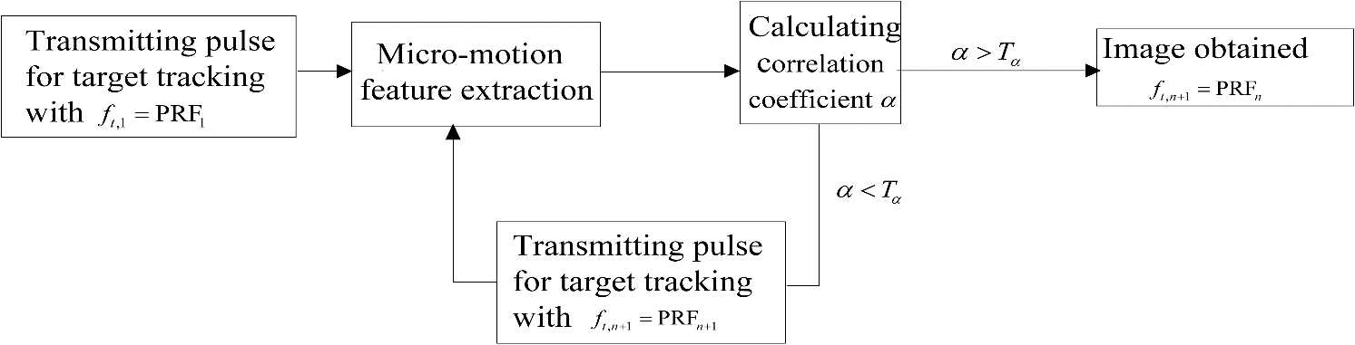 What should be pointed out is that with the condition of high-frequency scattering, the shielding effect can be easily induced by the spin motion because of the geometry of the target. In this case, a nonlinear shielding function needs to be introduced to describe the target scattering state, then the reflection coefficient of the th scatterer is . Without the loss of generality, assuming obeys the Bernoulli distribution where is the shielding rate and denotes the possibility of scattering shielding. However, the shielding effect does not change the intrinsic characteristics of the radar echo signal, so the atom set is still reasonable and the proposed micromotion feature extraction method from the tracking pulse can also successfully extract the micromotion features of the target.4.Experimental ResultsTo validate the effectiveness of the micromotion feature extraction method with varying PRF sampling based on the OMP, simulations are given in this section. The pulse duration is and the carrier frequency is . The radar is located at the origin of the coordinate system, and the coordinate of the target reference point is (0, 1000, 1700) km. The target consists of three rotational scatterers whose coordinates are , , and , respectively, in meters relative to the reference point in the rotating plane. The flight speed of the target is , the target is rotating around the -axis, and its rotation velocity is . The distribution of the target scatterer in the imaging plane is shown in Fig. 3. The observation duration is . The signals are sampled with a at the first 0.6 s, sampled with a PRF of 15 Hz between 0.6 to 1.2 s, and sampled with a PRF of 19 Hz for the final 0.8 s. Obviously, each PRF does not satisfy , and the time-frequency analysis of the echo signal while varying the PRF sampling is as shown in Fig. 4. From Fig. 4, it can be seen that the micromotion feature of the target cannot be extracted due to aliasing. However, the micromotion feature extraction of the target can be implemented with the method proposed in Sec. 2 of this paper. Setting the maximum iteration count at , the threshold of the residual signal energy is . The result of the micromotion feature extraction of the target is shown in Table 1. The target’s image can be obtained as shown in Fig. 5(a), and the time-frequency distribution of the reconstructed signal from the decomposition result is shown in Fig. 5(b). Table 1Micromotion features extracted with varying PRF sampling.
Fig. 5Image of the target reconstructed using Orthogonal Matching Pursuit (OMP) method and the time-frequency distribution of the reconstructed signal for noise-free case. (a) The target image by OMP. (b) The time-frequency distribution of the reconstructed signal from the decomposition result.  From Table 1, we can see that the algorithm can successfully extract the micromotion features of the three scatterers with be 5.0, 5.9, and 6.0 m, be , and be , , and , respectively, which are close to the original real parameters. It should be pointed out that four groups of feature parameters are extracted since the maximum iteration number in the OMP algorithm has been set as 4. Table 1 indicates that as the iteration increases, the energy of the extracted signal decreases correspondingly, and the fourth group of feature parameters corresponds to the residual signal with the lowest energy. The target image shown in Fig. 5(a) is almost identical to the scatterers shown in Fig. 3. The time-frequency distribution of the reconstructed signal from the decomposition result also reinforces the correctness of the results. To validate the robustness of the algorithm, Gaussian noise with is added into the echo signal. The echo signal of the target is sampled with varying PRF, and then the micromotion feature extraction of the target is implemented with the proposed method. The result is shown in Table 2. The image reconstructed from the extracted parameter and coefficient is shown in Fig. 6(a), and the time-frequency distribution of the reconstructed signals from the decomposition result is shown in Fig. 6(b). Table 2Micromotion features extracted with varying PRF sampling (SNR=0 dB).
Fig. 6Image of the target reconstructed using OMP method and the time-frequency distribution of the reconstructed signal for . (a) The target image by OMP. (b) The time-frequency distribution of the reconstructed signal from the decomposition result.  From Table 2, we can see that the algorithm can successfully extract the micromotion features of the three scatterers with a low . The image shown in Fig. 6(a) is almost identical to the distribution of the target scatterers. However, when SNR is reduced to , the micromotion features cannot be correctly extracted with the algorithm. The previous simulations have been carried out with varying PRFs (0.6 s at 13 Hz, 0.6 s at 15 Hz, and 0.8 s at 19 Hz). Next, we carried out the micromotion feature extraction method with an adaptive PRF. We stepped the correlation of the images through the set of tracking data rate: , , , , , , and . The interval of the micromotion feature extraction of the target based on the OMP algorithm is , and the threshold of the correlation coefficient of the target images from the adjacent times is . The plot of the correlation coefficient of the images from each adjacent two time-intervals is shown in Fig. 7. We can see that the correlation coefficient reaches the threshold after the fifth micromotion feature extraction, and the target tracking data rate is , much smaller than the 19 Hz used in the previous simulations; here, the extracted micromotion feature is shown in Table 3 and the image reconstructed from the extracted parameter is shown in Fig. 8. Table 3Micromotion features extracted from the tracking pulse with adaptive PRF.
To highlight the advantage of the proposed algorithm, the traditional micromotion feature extraction method based on TFD-Hough transform is used for comparison. Assume that satisfies to avoid the spectrum-aliasing problem. The micromotion features extracted by the TFD-Hough transform are shown in Table 4. From Table 4, we can see that the precision of the TFD-Hough transform is not satisfactory because the method is limited by the time-frequency resolution. Also, the TFD-Hough method needs 2-s continuous time resource for target observation with . Comparatively, the proposed micromotion feature extraction method using tracking pulses can obtain more precise extraction results without continuous time-resource allocation. As a result, the radar efficiency can be improved. Table 4Micromotion features extracted based on TFD-Hough.
Finally, we discussed the shielding effect of scatterers. Assume and , the time-frequency distribution of the radar echo signal is shown in Fig. 9. We can see that the shielding effect produces an adverse influence on the time-frequency distribution. In the final simulation, we implement the micromotion feature extraction method with an adaptive PRF under the shielding effect. The set of tracking data rate is the same as previous simulations, and the plot of the correlation coefficient of the images from each adjacent two time-intervals is shown in Fig. 10. We can see that the correlation coefficient reaches the threshold after the sixth micromotion feature extraction, and the target tracking data rate is . Here, the extracted micromotion feature is shown in Table 5 and the time-frequency distribution of the reconstructed signals from the decomposition result is shown in Fig. 11. The simulation shows the good performance of our proposed method under the shielding effect. Table 5Micromotion features extracted from the tracking pulse with adaptive PRF under shielding effect.
5.ConclusionTo lighten the demand on radar resources, a micromotion feature extraction method using tracking pulses with an adaptive PRF is proposed in this paper. With this method, the atom set of the micro-Doppler signals is constructed according to the prevailing tracking data rate, and the correlation of the images (constructed at the current and previous PRFs) is fed back to the radar system and used to adjust the PRF of the transmitted pulse and the dictionary atoms. The micromotion feature extraction of the target is then implemented using tracking pulses based on the OMP method. The steps of the method are described in detail, and the simulations are given to illustrate its effectiveness. Although the spinning target is taken as an example in this paper, the proposed method is also suitable for other micromotion targets such as vibration and precession targets. In fact, recognition of a target can be achieved according to the result of the micromotion target feature extraction of the target. On this basis, the tracking data rate can be adjusted again according to the different types of the targets. Meanwhile, the tracking property can be fed back to the radar system to adjust the tracking period. AcknowledgmentsThis work was supported in part by the National Natural Science Foundation of China under Grant 61201369 and 61172169 and in part by Natural Science Foundation Research Program of Shaanxi Province under Grant 2013JQ8008. ReferencesX. Baiet al.,
“High-resolution three-dimensional imaging of spinning space debris,”
IEEE Trans. Geosci. Remote Sens., 47
(7), 2352
–2362
(2009). http://dx.doi.org/10.1109/TGRS.2008.2010854 IGRSD2 0196-2892 Google Scholar
Y. Luoet al.,
“Micro-motion feature extraction of target in inverse synthetic aperture radar imaging with sparse aperture,”
J. Electromagn. Waves Appl., 27
(14), 1841
–1849
(2013). http://dx.doi.org/10.1080/09205071.2013.825890 JEWAE5 0920-5071 Google Scholar
J. Heet al.,
“Micro-Doppler effect analysis and feature extraction in inverse synthetic aperture imaging LADAR imaging,”
J. Appl. Remote Sens., 5
(1), 051502
(2011). http://dx.doi.org/10.1117/1.3652706 1931-3195 Google Scholar
K. Y. Guoet al.,
“Influence of migratory scattering phenomenon on micro-motion characteristics contained in radar signals,”
IET Radar Sonar Navig., 7
(5), 579
–589
(2013). http://dx.doi.org/10.1049/iet-rsn.2012.0058 1751-8784 Google Scholar
Y. Luoet al.,
“Micro-Doppler effect analysis and feature extraction in ISAR imaging with stepped-frequency chirp signals,”
IEEE Trans. Geosci. Remote Sens., 48
(4), 2087
–2098
(2010). http://dx.doi.org/10.1109/TGRS.2009.2034367 IGRSD2 0196-2892 Google Scholar
V. C. Chenet al.,
“Micro-Doppler effect in radar: phenomenon, model and simulation study,”
IEEE Trans. AES, 42
(1), 2
–21
(2006). http://dx.doi.org/10.1109/TAES.2006.1603402 IEARAX 0018-9251 Google Scholar
C. Wanget al.,
“Micro-Doppler feature extraction using single-frequency radar for high-speed targets,”
in Radar Conf. 2013, IET Int.,
1
–6
(2013). Google Scholar
Y. Renet al.,
“A space target recognition method based on compressive sensing,”
in 2011 Sixth Int. Conf. on Image and Graphics (ICIG),
582
–586
(2011). Google Scholar
T. ThayaparanL. StankovićI. Djurović,
“Micro-Doppler-based target detection and feature extraction in indoor and outdoor environments,”
J. Franklin Inst., 345
(6), 700
–722
(2008). http://dx.doi.org/10.1016/j.jfranklin.2008.01.003 JFINAB 0016-0032 Google Scholar
H. SunZ. Liu,
“Micro-Doppler feature extraction for ballistic missile warhead,”
in Int. Conf. on Information and Automation,
1333
–1336
(2008). Google Scholar
H. Gaoet al.,
“Micro-Doppler signature extraction from ballistic target with micro-motions,”
IEEE Trans. AES, 46
(4), 1969
–1982
(2010). http://dx.doi.org/10.1109/TAES.2010.5595607 IEARAX 0018-9251 Google Scholar
D. Zhanget al.,
“The study of three-dimensional micro-motion feature extraction of ballistic target based on netted radar,”
Appl. Mech. Mater., 530–531 534
–539
(2014). http://dx.doi.org/10.4028/www.scientific.net/AMM.530-531 AMMPDO 1662-7482 Google Scholar
T. Thayaparan,
“Analysis of radar micro-Doppler signatures from experimental helicopter and human data,”
IET Radar, Sonar & Navig., 1
(4), 289
–299
(2007). http://dx.doi.org/10.1049/iet-rsn:20060103 1751-8784 Google Scholar
J. LiH. Ling,
“Application of adaptive chirplet representation for ISAR feature extraction from targets with rotating parts,”
IEE Proc. Radar Sonar Navig., 150
(4), 284
–291
(2003). http://dx.doi.org/10.1049/ip-rsn:20030729 IRSNE2 1350-2395 Google Scholar
Y. LiL. DuH. Liu,
“Hierarchical classification of moving vehicles based on empirical mode decomposition of micro-Doppler signatures,”
IEEE Trans. Geosci. Remote Sens., 51
(5), 3001
–3013
(2013). http://dx.doi.org/10.1109/TGRS.2012.2216885 IGRSD2 0196-2892 Google Scholar
L. Duet al.,
“Robust classification scheme for airplane targets with low resolution radar based on EMD-CLEAN feature extraction method,”
Sens. J., 13
(12), 4648
–4662
(2013). http://dx.doi.org/10.1109/JSEN.2013.2272119 ISJEAZ 1530-437X Google Scholar
X. Chenet al.,
“Maneuvering target detection via radon-fractional Fourier transform-based long-time coherent integration,”
IEEE Trans. Signal Process., 62
(4), 939
–953
(2014). http://dx.doi.org/10.1109/TSP.2013.2297682 ITPRED 1053-587X Google Scholar
Q. Zhanget al.,
“Imaging of a moving target with rotating parts based on the Hough transform,”
IEEE Trans. Geosci. Remote Sens., 46
(1), 291
–299
(2008). http://dx.doi.org/10.1109/TGRS.2007.907105 IGRSD2 0196-2892 Google Scholar
Y. Lianget al.,
“Analysis and extraction of micro-Doppler features in FMCW-ISAR using a modified extended Hough transform,”
in 2011 IEEE CIE Int. Conf. on Radar,
1652
–1655
(2011). Google Scholar
Y. L. WangY. N. PengZ. Bao,
“Space-time adaptive processing for airborne radar with various array orientations,”
IET Radar Sonar Navig., 144
(6), 330
–340
(1997). http://dx.doi.org/10.1049/ip-rsn:19971606 1751-8784 Google Scholar
M. RueggE. MeierD. Nuesch,
“Vibration and rotation in millimeter-wave SAR,”
IEEE Trans. Geosci. Remote Sens., 45
(2), 293
–304
(2007). http://dx.doi.org/10.1109/TGRS.2006.887025 IGRSD2 0196-2892 Google Scholar
D. NeedellR. Vershynin,
“Signal recovery from incomplete and inaccurate measurements via regularized orthogonal matching pursuit,”
IEEE J. Sel. Top. Signal Process., 4
(2), 310
–316
(2010). http://dx.doi.org/10.1109/JSTSP.2010.2042412 1932-4553 Google Scholar
Y. Luoet al.,
“Micro-Doppler feature extraction for wideband imaging radar based on complex image orthogonal matching pursuit decomposition,”
IET Radar Sonar Navig., 7
(8), 914
–924
(2013). http://dx.doi.org/10.1049/iet-rsn.2012.0327 1751-8784 Google Scholar
BiographyYijun Chen received her MS degree in electrical engineering from the Institute of Information and Navigation, Air Force Engineering University (AFEU), Xi’an, China, in 2013, where she is currently working toward the PhD degree in electrical engineering. She is currently with the Radar and Signal Processing Laboratory, Institute of Information and Navigation, AFEU. Her research interests include signal processing and cognitive radar. Qun Zhang received his MS degree in mathematics from Shaanxi Normal University, Xi’an, China, in 1988, and the PhD degree in electrical engineering from Xidian University, Xi’an, in 2001. He is a senior member of the Chinese Institute of Electronics (CIE), a committee member of the Radiolocation Techniques Branch, CIE. He was also a vice co-chair of the Technical Program Committee of Workshop for Space, Aeronautical and Navigational Electronics (WSANE), 2009. Changzheng Ma received his BS degree from Lanzhou University, Lanzhou, China, in 1989, the MS degree from the Chinese Academy of Sciences, Beijing, China, in 1992, and the PhD degree from Xidian University, Xi’an, China, in 1999. He is currently a research fellow with the Department of Electrical and Computer Engineering, National University of Singapore, Singapore. His research interests include signal processing, radar imaging, and wireless communication. Ying Luo received his MS degree in electrical engineering from the Institute of Information and Navigation, Air Force Engineering University (AFEU), Xi’an, China, in 2008, and the PhD degree in electrical engineering from AFEU, Xi’an, in 2013. He is currently with the Radar and Signal Processing Laboratory, Institute of Information and Navigation, AFEU. His research interests include signal processing and ATR in SAR and ISAR. Tat Soon Yeo received his B.Eng. (Honors I) degree from the University of Singapore, Singapore, in 1979, the M.Eng. degree from the National University of Singapore (NUS), Singapore, in 1981, and the PhD degree from the University of Canterbury, New Zealand, in 1985, under a Colombo Plan Scholarship. He received the MINDEF-NUS Joint R&D Award in 1997 and the IEEE Millennium Medal in 2000. |


